How to assemble a touch switch with your own hands: description of the device and assembly diagram
Electronic technology covers a wide range of household applications. There are practically no restrictions. Even the simplest functions of the lamp switch of household lamps are now increasingly performed by touch devices, rather than technologically obsolete ones - manual ones.
Electronic devices, as a rule, are included in the category of complex structures. Meanwhile, to build a touch switch with your own hands, as practice shows, is not difficult at all. Minimum experience in the design of electronic devices for this is quite enough.
We offer to understand the device, functionality and connection rules of such a switch. For lovers of homemade products, we have prepared three working schemes for assembling an intelligent device that can be implemented at home.
The content of the article:
Touch Switch Design
The term “sensory” carries a fairly broad definition. In fact, under it should be considered a whole group of sensors that can respond to a variety of signals.
However, in relation to switches - devices endowed with the functionality of switches, the touch effect is most often considered as the effect obtained from the energy of the electrostatic field.
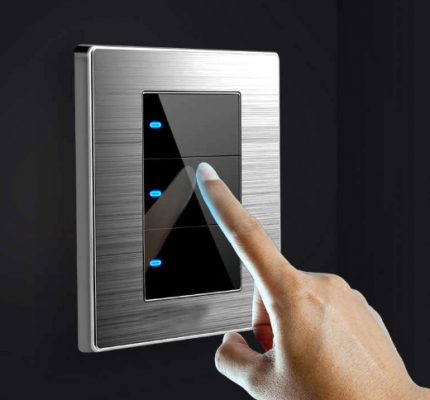
An ordinary user just needs to touch such a contact field with his fingers and the same switching result will be obtained in response as a standard familiar keyboard device.
Meanwhile, the internal structure of the sensor equipment is significantly different from a simple manual switch.
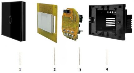
Typically, this design is built on the basis of four working nodes:
- protective panel;
- contact sensor-sensor;
- electronic board;
- device case.
The variety of devices based on sensors is extensive.Models with the functions of conventional switches are available. And there are more advanced developments - with brightness controls that monitor the temperature of the environment, raise the blinds on the windows and others.
Not only are all these kinds of switches controlled by a light touch, there are still remote control switches. That is, the user can turn off the lamp or remove the brightness of the lamp glow of the device without making unnecessary movements in the form of a transition from a resting place to a switch.
Device Options and Capabilities
Separate consideration clearly deserve timer switches.
There are traditional characteristics, such as:
- silent operation;
- interesting design;
- safe use.
In addition to all this, another useful feature is added - a built-in timer. With it, the user gets the ability to manage the switch programmatically. For example, set the on and off time in a certain time range.
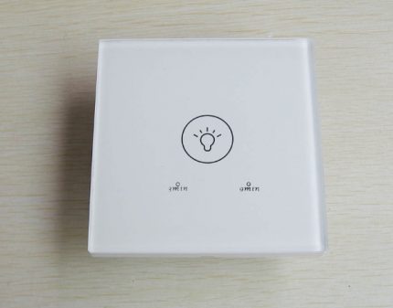
As a rule, such devices have not only a timer, but also an accessory of a different kind - for example, an acoustic sensor.
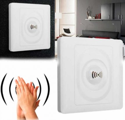
In this embodiment, the device acts as a motion or noise controller. It is enough to cast a voice or clap your palms and the lamp lamps in the apartment light up with a bright light.
By the way, in case of too high brightness, there is another functional - dimmer adjustment. Touch-type switches equipped with a dimmer allow you to control the light intensity.
True, there is one caveat for such developments. Dimmers, as a rule, do not support the use of fluorescent and LED lamps in luminaires. But eliminating this shortcoming is most likely a matter of time.
Read more about varieties of “smart” light switches in this article.
Instrument Connection Rules
The installation technology of such devices, despite the perfection of designs, has remained traditional, as provided for standard light switches.
Typically, there are two terminal contacts on the back of the product’s case - input and load. Are designated on devices of foreign manufacture by markers "L-in" and "L-load".
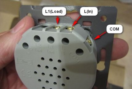
These designations should be clear even to an inexperienced user. However, in any case, it is recommended to refer to the device passport before installing it. Switching in the device circuit is carried out on a phase line.
That is, a phase is applied to the L-in input - a phase conductor is connected. And from the “L-load" line the voltage is removed for the load - in particular, for the lamp of the lamp.
Meanwhile, the design of touch switches may include the connection of several independent loads. On such devices, the number of terminals for connection increases.
Additionally, with the input voltage terminal "L-in" there are already two or even three holes for the load "L-load". Typically labeled something like this: "L1-load", "L2-load", etc.
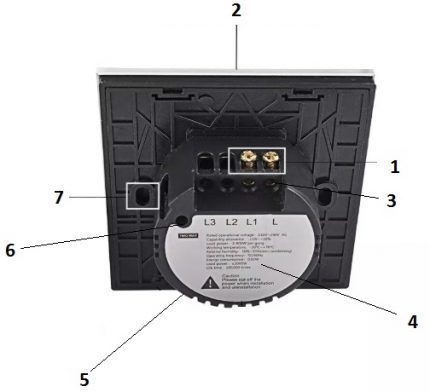
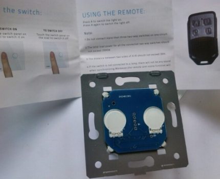
Installation of touch switches is also virtually no different from the standard version. The design of the switches is made for placement in traditional socket boxes. Mounting the chassis of the working mechanism of the device, as a rule, is carried out by screws.
DIY switch on sensors
Buying a touch-type switch for home use is certainly not a problem. However, the cost of these kind of intelligent devices starts from 1500-2000 rubles. And this is the price of not the most advanced designs. Therefore, the question seems logical - is it possible to make sensory light switching with your own hands?
For people who are more or less familiar with the theory of electrical engineering, the construction of a switch using a sensor is quite feasible. There are a lot of circuit solutions in this regard.
Scheme of the touch switch on the trigger
Many schemes for making devices of this kind are simple and straightforward. Consider one of the many solutions that you can implement with your own hands for use at home.
The K561TM2 series chip, widely used in amateur radio practice, is the main link in a do-it-yourself touch switch.
The K561TM chip is a trigger whose state can be changed by supplying a control signal to its input. This property has been successfully used to implement the switch function.
The input circuit is built with the addition of a field-effect transistor V11, which provides high input sensitivity and additionally isolates the input from the output.
The sensor element E1 of the circuit is made in the form of a metal plate and is connected to the input of the field controller through a resistor with high resistance. This ensures the safety of the device for the user in terms of possible electric shock.
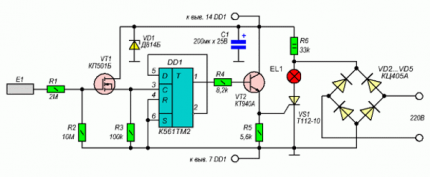
The output part of the circuit is built on a bunch of bipolar transistor VT2 - current thyristor VS1. The transistor amplifies the signal coming from the microcircuit, and the thyristor acts as a switch. The lighting device that you want to control is included in the thyristor circuit.
The scheme works like this:
- The user touches a metal plate (sensor).
- Static electricity enters the VT input.
- The field effect transistor switches the trigger.
- The trigger output is amplified by VT2 and opens the thyristor.
- The lamp in the thyristor circuit lights up.
If the user touches the sensor again, all operations are repeated, but with the reverse switching of modes. Everything is simple and effective.
Such a circuit solution can be used to control fixtures, where the total power of incandescent lamps is not higher than 60 watts.
If it is necessary to switch more powerful light devices, you can supplement the thyristor with a volume cooling radiator. It is recommended to use metal for the sensor from a series of materials that conduct well current. The best option is silver plated copper.
Infrared Sensor Circuit
A light switch circuit is available for self-assembly, where an IR sensor is used as a sensor. It also uses affordable and affordable electronic components.
According to the degree of complexity of execution, this option is designed for electronic engineers who are just starting their career.
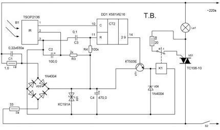
The base electronics in this solution are two microcircuits and the following elements:
- regular LED - HL1;
- infrared LED - HL2;
- photodetector - U1;
- Relay - K1.
A pulse generator is assembled on the basis of the DD1 inverter chip, and a system counter is functioning on the basis of the DD2 chip.
Under certain circumstances, for example, when a biological object appears in the area of the infrared LED, a pair of IR LEDs and a photodetector are triggered. Based on the transistor VT1, a control signal appears, which turns on the relay K1. The lamp in the K1 circuit lights up.
If the movement of objects in the coverage area of the infrared sensor is not detected, after 20 minutes of inactivity the counter will count the number of pulses from the flashing LED HL1, sufficient to turn off the relay. The lamp will turn off. The waiting time (in this case 20 minutes) is determined by the selection of circuit elements.
The simplest circuit on transistors and relays
The most simplified solution is the scheme for self-assembly of the sensor type device, which is presented below.
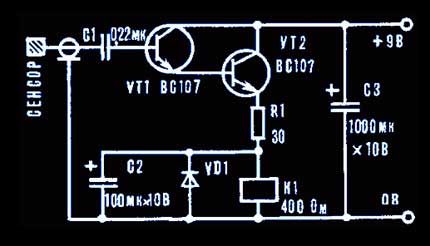
It is permissible to use almost any type of relay here. The main criterion is the range of operating voltages of 6-12 volts and the ability to switch the load in the network 220 volts.
The sensor element is made by cutting out a sheet of foil-coated getinax. Transistors can also be used in any series, similar in parameters specified, for example, common KT315.
In fact, this simple circuit represents a conventional signal amplifier. When touching the surface of the sensor based on the transistor VT1, a potential appears sufficient to open the emitter-collector junction.
Next, VT2 transition opens and the supply voltage is supplied to the relay coil K1. This device is triggered, its contact group closes, which leads to the inclusion of a light device.
If you do not want to experiment and assemble the device yourself, you can buy a ready-made switch and install it yourself. All the necessary information about the selection and connection of the touch switch is set out here.
Conclusions and useful video on the topic
This review allows you to get to know the light switches that are rapidly gaining popularity in society.
Touch switches marked with the Livolo product brand - what are these designs and how attractive they are to the end user. A video guide on new types of switches will help you get answers to questions:
Concluding the topic of touch switches, it is worth noting the active development in the field of development and production of switches for domestic and industrial use.
The light switches, it would seem, the simplest designs, are so perfect that now you can control the light with a voice code phrase and at the same time get complete information about the state of the atmosphere inside the room.
Have something to supplement, or have questions about assembling the touch switch? You can leave comments on the publication, participate in discussions and share your own experience in using such devices. The contact form is located in the lower block.

 Touch light switch: why is it needed, types, marking, selection and connection
  Cross circuit breaker: purpose and device + wiring diagram and installation
 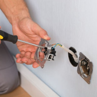 How to connect a passage switch: circuit analysis + step-by-step connection instructions
 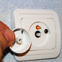 How to connect a dimmer: possible schemes + instructions for connecting with your own hands
 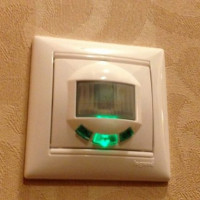 Switch with motion sensor: how to choose and install a light switch with a sensor
 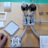 Two-way walk-through switch: device + wiring diagram + installation tips
  How much does it cost to connect gas to a private house: the price of organizing gas supply
  The best washing machines with dryer: model rating and customer tips
  What is the color temperature of light and the nuances of choosing the temperature of the lamps to suit your needs
  Replacement of a geyser in an apartment: replacement paperwork + basic norms and requirements
I read it, and mentally turned out to be in 1980, holding the “Do it yourself” magazine. It was in those days that turning on the lighting in the bedroom was considered “the pinnacle of modern technology”, and the presence of a motion sensor in the corridor was an indicator of a technically advanced resident of the apartment. Transistors, thyristors, microcircuit, sensor, relay coil - do I need to write about this? Say that a ready-made device is expensive in the store, and it will be cheaper to make it with your own hands? Believe me, the time spent on making a device will be much more expensive.
Sergey, do-it-yourselfers often do something not for saving money, but for pleasure.
There are affairs for an hour or two, no more. If for Moscow it is still realistic to receive, for the regions almost the entire population does not have such a salary. Therefore, the time spent can be more expensive only if you live in Moscow or work in Gazprom. In all other cases, it is much cheaper to do it yourself. Dot.
I made the simplest circuit on 2 transistors back in the 80s ... She still “works”, and it’s a lie that it’s cheaper to buy ready-made. I still do all sorts of homemade products and not always for the sake of money.
Pavel. I urge you. Send a working diagram of the touch network switch. I want to collect and check. Let your circuit work for me too.
The scheme is wrong, it will not work.