Calculation of a single-pipe heating system: what to consider when calculating + practically an example
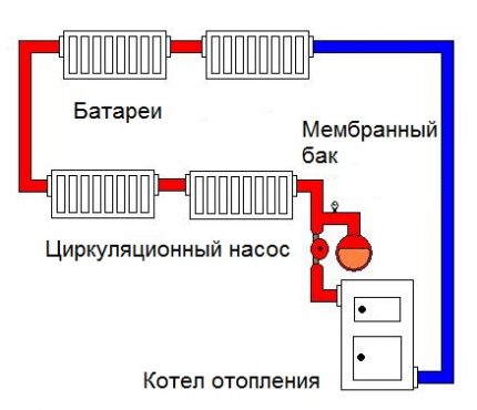
One-pipe heating system is one of the solutions for piping inside buildings with the connection of heating devices. Such a scheme seems most simple and effective. The construction of a heating branch according to the “one pipe” option costs homeowners cheaper than other methods.
To ensure the operation of the circuit, it is necessary to carry out a preliminary calculation of a single-pipe heating system - this will maintain the desired temperature in the house and prevent loss of pressure in the network. It is quite possible to cope with this task on your own. Doubt your strength?
We will tell you what are the features of a single-tube system, give examples of working schemes, explain what calculations should be performed at the planning stage of the heating circuit.
The content of the article:
The device of a one-pipe heating circuit
The hydraulic stability of the system is traditionally ensured by the optimal selection of the conditional passage of pipelines (Dsl). It is quite simple to implement a stable scheme by the method of selecting diameters, without first setting up heating systems with temperature controllers.
It is to such heating systems that a direct relationship has single pipe with vertical / horizontal installation of radiators and in the complete absence of shut-off and control valves on risers (branches to devices).
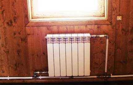
Using the method of changing the pipe diameters in a single-tube ring heating circuit, it is possible to balance the pressure losses that occur quite accurately. The control of coolant flows inside each individual heating device provides setting the thermostat.
Usually, as part of the process of constructing a heating system according to a one-pipe scheme, at the first stage, nodes for binding radiators are built.At the second stage, the circulation rings are linked.
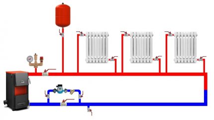
The design of the binding unit of a single device involves the determination of pressure losses on the node. The calculation is carried out taking into account the uniform distribution of the coolant flow by the temperature controller relative to the connection points in this circuit section.
In the framework of the same operation, the calculation of the leakage coefficient is performed, plus the determination of the range of flow distribution parameters in the closing section. Already relying on the calculated range of branches, a circulation ring is built.
Linking circulation rings
In order to perform high-quality alignment of the circulation rings of a single-tube circuit, a preliminary calculation is made of possible pressure losses (∆Ро). In this case, the pressure loss at the control valve (∆Рк) is not taken into account.
Further, by the value of the coolant flow rate at the final section of the circulation ring and by the value of ∆Рк (the graph in the technical documentation for the device), the adjustment value of the control valve is determined.
The same indicator can be determined by the formula:
Kv = 0.316G / √∆Рк,
Where:
- Sq - setting value;
- G - coolant flow rate;
- ∆Рк - pressure loss on the control valve.
Similar calculations are performed for each individual control valve in a single pipe system.
True, the range of pressure losses on each PB is calculated by the formula:
∆Рко = ∆Ро + ∆Рк - ∆Рn,
Where:
- ∆Ро - possible pressure loss;
- ∆Рк - pressure loss on the PB;
- ∆Pn - pressure loss in the area of the n-circulation ring (excluding losses in the RS).
If, as a result of calculations, the necessary values for a single-pipe heating system as a whole have not been obtained, it is recommended to use the option of a single-pipe system, which includes automatic flow controllers.
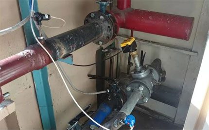
Devices such as automatic regulators are mounted on the end sections of the circuit (connection points on risers, branch branches) at the points of connection to the return line.
If you technically change the configuration of the automatic controller (swap the drain valve and plug), the installation of devices is possible on the coolant supply lines.
With the help of automatic flow controllers, the circulation rings are linked. In this case, the pressure loss ∆Рс at the end sections (risers, instrument branches) is determined.
The residual pressure loss within the circulation ring is distributed between the common sections of the pipelines (∆Pmr) and the general flow regulator (∆Pp).
The value of the temporary adjustment of the general controller is selected according to the graphs presented in the technical documentation, taking into account ∆Рмр of the end sections.
Calculate the pressure loss at the end sections by the formula:
∆Рс = ∆Рп - ∆Рмр - ∆Рр,
Where:
- ∆Рр - estimated value;
- ∆Rpp - set pressure drop;
- ∆Рмр - Rrab losses in pipeline sections;
- ∆Рр - Loss of Rrab in the general RV.
The automatic regulator of the main circulation ring is set (provided that the pressure differential is not initially set) taking into account the installation of the minimum possible value from the setting range in the technical documentation of the device.
The quality of the controllability of the flows by the automation of the general regulator is controlled by the difference in pressure loss on each individual riser regulator or instrument branch.
Application and Business Case
The absence of requirements for the temperature of the cooled coolant is the starting point for the design of single-pipe heating systems on thermostats with the installation of TR on the radiator supply lines.At the same time, it is mandatory to equip the heat point with automatic adjustment.
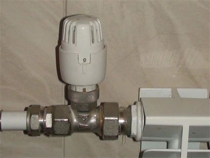
Schematic solutions, where there are no thermoregulating devices on radiator supply lines, are also used in practice. But the use of such schemes is due to slightly different microclimate priorities.
Typically, single-tube schemes, where there is no automatic control, are used for groups of rooms designed to compensate for heat losses (50% or more) due to additional devices: forced ventilation, air conditioning, electric heating.
Also, the device of single-tube systems is found in projects where the temperature limits for the coolant exceeding the limit value of the operating range of the thermostat are allowed by the standards.
Projects of apartment buildings, where the operation of the heating system is tied to the heat consumption by means of meters, is usually built on a perimeter single-pipe scheme.
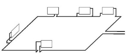
The economic justification for the implementation of such a scheme is the location of the main risers at different points in the structure.
The main calculation criteria are the cost of two main materials: heating pipes and fittings.
According to practical examples of the implementation of the perimeter single pipe system, an increase in the Du cross section of pipelines by a factor of two is accompanied by an increase in the cost of purchasing pipes by a factor of 2-3. And the costs of fittings increase to 10 times the size, depending on what material the fittings are made of.
Settlement base for installation
Installation of a single-tube circuit, from the point of view of the location of the working elements, practically does not differ from the device of the same double pipe systems. Trunk risers are usually located outside the living quarters.
SNiP rules recommend laying the risers inside special mines or gutters. The apartment line is traditionally built around the perimeter.
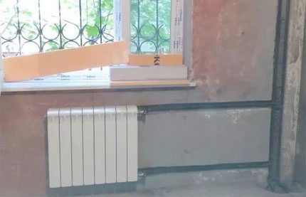
Laying of pipelines is carried out at a height of 70-100 mm from the upper boundary of the floor plinth. Or installation is done under a decorative plinth with a height of 100 mm or more and a width of up to 40 mm. Modern production produces such specialized linings for the installation of plumbing or electrical communications.
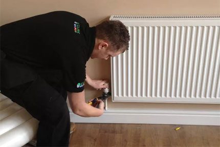
Tying radiators is performed by a top-down scheme with a supply of pipes on one side or on both sides. The location of the thermostats “on a specific side” is not critical, but if installation of a heating device It is carried out next to the balcony door, TP installation is carried out necessarily on the side farthest from the door.
Laying pipes behind the baseboard seems predominant from a decorative point of view, but it makes you recall the disadvantages when it comes to passing areas where there are interior doorways.
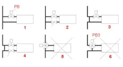
The connection of heating devices (radiators) with single-pipe risers is carried out according to schemes that allow slight linear elongation of pipes or according to schemes with compensation for elongation of pipes as a result of temperature changes.
The third version of the circuit solutions, where the use of a three-way controller is supposed, is not recommended for reasons of economy.
If the device of the system provides for the installation of risers hidden in the gates of the walls, it is recommended to use angle thermostats of the RTD-G type and shut-off valves similar to devices from the RLV series as connecting fittings.
The diameter of the pipe branch to the heating devices is calculated by the formula:
D> = 0.7√V,
Where:
- 0,7 - coefficient;
- V - the internal volume of the radiator.
The branch is performed with a certain slope (at least 5%) in the direction of the free exit of the coolant.
Selection of the main circulation ring
If the design solution involves a heating system based on several circulation rings, the choice of the main circulation ring is necessary. The choice theoretically (and practically) should be made according to the maximum heat transfer value of the most remote radiator.
This parameter to some extent affects the assessment of the hydraulic load as a whole attributable to the circulation ring.
The heat transfer of a remote device is calculated by the formula:
ATP = Qv / Qop + ΣQop,
Where:
- Atp - estimated heat transfer of the remote device;
- Qv - the necessary heat transfer of the remote device;
- Qop - heat transfer from radiators to the room;
- ΣQop - the sum of the necessary heat transfer of all devices in the system.
In this case, the parameter of the amount of necessary heat transfer may consist of the sum of the values of devices designed to serve the building as a whole or only part of the building. For example, when calculating heat separately for rooms covered by one separate riser or separately taken areas serviced by the instrument branch.
In general, the calculated heat transfer of any other heating radiator installed in the system is calculated by a slightly different formula:
ATP = Qop / Qpom,
Where:
- Qop - the necessary heat transfer for a separate radiator;
- Qhom - thermal demand for a particular room where a single-tube scheme is used.
The easiest way to deal with the calculations and the application of the obtained values is on a specific example.
Practical calculation example
For a residential building, a one-pipe system with control from a thermostat is required.
The value of the nominal throughput of the device at the maximum setting border is 0.6 m3/ h / bar (k1). The maximum possible throughput characteristic for this setting value is 0.9 m3/ h / bar (K2).
The maximum possible pressure difference TP (at a noise level of 30 dB) is not more than 27 kPa (ΔP1). Pump head 25 kPa (ΔP2) The operating pressure for the heating system is 20 kPa (ΔP).
It is necessary to determine the pressure loss range for TP (ΔP1).
The value of internal heat transfer is calculated as follows: Atr = 1 - k1 / k2 (1 - 06/09) = 0.56. From here, the required range of pressure losses on the TP is calculated: ΔP1 = ΔP * Atr (20 * 0.56 ... 1) = 11.2 ... 20 kPa.
If independent calculations lead to unexpected results, it is better to contact specialists or use a computer calculator to check.
Conclusions and useful video on the topic
A detailed analysis of the calculations using a computer program with explanations on the installation and improvement of system functionality:
It should be noted that a full-scale calculation of even the simplest solutions is accompanied by a mass of calculated parameters. Of course, it is fair to calculate everything without exception, provided that a heating structure is organized that is close to an ideal structure. However, in reality there is nothing perfect.
Therefore, they often rely on calculations as such, as well as practical examples and the results of these examples. This approach is especially popular for private housing construction.
Is there anything to supplement, or have questions about calculating a single-pipe heating system? You can leave comments on the publication, participate in discussions and share your own experience in arranging the heating circuit. The contact form is located in the lower block.

 Thermal calculation of a heating system: how to correctly calculate the load on a system
  Hydraulic calculation of the heating system on a specific example
  Calculation of air heating: basic principles + calculation example
  Calculation of the heating system of a private house: rules and examples of calculation
  Calculation of water heating: formulas, rules, examples of implementation
  How to arrange the heating of a private house with your own hands: schemes for organizing an autonomous heating system
  How much does it cost to connect gas to a private house: the price of organizing gas supply
  The best washing machines with dryer: model rating and customer tips
  What is the color temperature of light and the nuances of choosing the temperature of the lamps to suit your needs
  Replacement of a geyser in an apartment: replacement paperwork + basic norms and requirements
The correct installation of the heating system in the house, in my opinion, is one of the most important points in the construction of the house. At one time, when I was doing heating in my house, I used a horizontal method of connecting radiators and laid pipes for heating on the floors. I also consider it important to choose the right pump, since with a horizontal wiring diagram, the movement of the coolant must be stimulated by the circulation unit.