How to check the grounding in the outlet: methods of testing using devices
Electrical outlets are accessories familiar to a potential user. They are used everywhere: in the house, at work, in public places, etc. According to technical standards, sockets must be grounded - this will protect households from electric shock when electrical appliances break down.
However, you must admit that it is unlikely that any of the consumers can confidently say that all the outlets in the house or apartment are grounded. To find out the location of the wires in the wiring, you need to conduct a series of tests.
We will tell you how to check the grounding in the socket in various ways - according to external signs and using special tools.
The content of the article:
Typical outlet design
The use of receptacle grounding verification techniques may be required at any time. Especially for those people who have to work with specific electrical outlets repeatedly.
This part of the electrical network (household or industrial) has a simple structure.
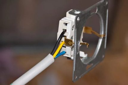
The electric socket consists of a round or rectangular plateau. A plateau is made based on materials that do not conduct electricity.
Typically, for the manufacture of a plateau of outlets used:
- ceramics;
- china;
- plastic.
The back of the plateau has a flat surface, and on the front there are curly landing pads for electric contactors. The material of the contactors is usually copper. The contactors are fixed on the plate tightly - with the help of rivets, plus they are embedded in the body of the plateau.
To connect to the electrical wiring, the contactors have fixing screws. This whole structure is closed by a lid having two passage openings for an electric plug.
Types of electrical outlets
The industry produces two types of products:
- equipped with a ground bus;
- not having a ground bus.
The first type of structure is often called the "Euro-socket". This design fully meets the requirements of electrical safety. When changing wiring recommend install ground outlets.
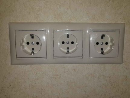
The second type of product is considered an obsolete modification, but is still found in practice. Especially a lot of outdated sockets are used in old buildings.

Both types of products are made for internal or external installation. According to the new PEB recommendations, modifications of sockets for internal installation should include bimetallic plates with a ground contactor as part of the design.
For electrical outlets for external installation, the recommendations are the same, but in some cases their use is allowed two-wire interface.
Grounding the outlet and test methods
Checking for grounding on electrical networks may be required in different cases:
- when changing your place of residence;
- in case of rental of any real estate;
- when buying an office or business;
- when doing work on a third-party territory, etc.
Consider common verification methods.
External check
The initial and simplest check for the presence of grounding is done visually by external signs. It is enough for a potential user to evaluate the external interface of the electrical outlet to draw certain conclusions for himself.
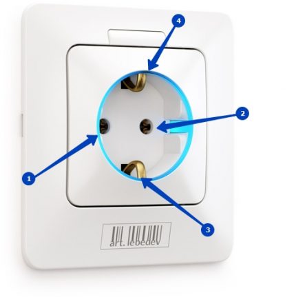
So, if characteristic details indicating the presence of a grounding bus are present inside the outlet bowl, 50% testing can be considered successful. Such details are special slots in the product body and contact bimetallic plates looking through these slots.
These grounding “whiskers” are usually located in the upper and lower regions of the outlet bowl.
Analysis of the internal "filling"
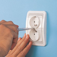
To make sure that the outlet is grounded with a 75% probability, you have to open the product body - unscrew one screw that holds the socket cover and remove it.
But before doing this work, you should disconnect the electrical communications - turn off the power input automaton, which is usually installed inside the mounting panel box, which is located on the staircase of the staircase (option for municipal housing).
After opening the outlet, the user will see the entire existing layout of conductors connected to the mounting terminals of the device.
For the circuit for the execution of the "euro", a characteristic sign of the wiring is the presence of three conductors:
- phase;
- zero;
- grounding.
May differ wire colors first two conductors. However, according to the established specifications, the phase is usually supplied with a wire with insulation colors brown or white, and zero with insulation colors blue or black. But in practice, everything can be very different.
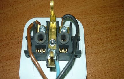
The third conductor is grounding, it is specifically painted in green or yellow-green. In addition, this wire, as a rule, has an enlarged section.The ground conductor inside the housing of the outlet is connected to the contact of the bus, which, in turn, has a direct connection with the bimetallic plates of the "euro" interface.
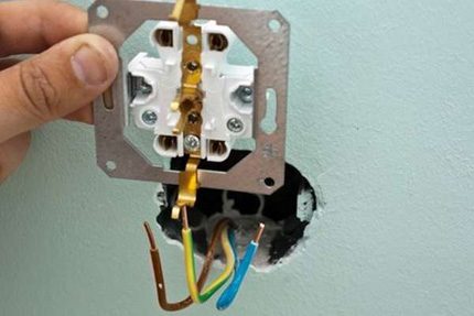
So, the presence of a connected wire (yellow-green, green) on the ground bus is already a 75% guarantee that the grounding in the socket is done.
It remains only to check the operability (integrity) of the grounding bus using special devices.
Instrument Testing
Testing technique with control devices gives a 100% guarantee of the presence of grounding in the socket. But the method of verification with the help of special devices is allowed to be used only by persons with appropriate tolerances. This is an important point, because testing with devices, as a rule, is performed with the voltage connected.
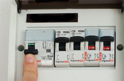
Household sockets are powered by voltage 220 V (sometimes voltage 110 V). When the power is connected, it becomes a real danger for people testing the elements of the power supply network. Especially for those who do not have a clue about the principle of operation of electric networks.
Incandescent lamp test
The first simple way of checking is done using a conventional incandescent lamp, designed for the voltage of an existing network.
The inspecting person for work needs to make simple equipment:
- Take an electric lamp holder.
- Connect a two-wire wire (20-30 cm) to the cartridge.
- Screw in incandescent bulb.
The ends of the cartridge conductors must be stripped 7-10 mm from the edge. If the conductors are stranded, the conductors of the stripped ends should be tightly twisted. For greater safety, you can equip the wire lugs. This completes the preparation of the snap, you can proceed directly to the test.
The following photo gallery will demonstrate the process of determining grounding using a light bulb:
Include circuit power machinewhere the outlet goes. Take a cartridge with a lamp and connect the ends of the wire to the usual contactors of the outlet (phase - zero). The lamp should shine brightly. Such a connection indicates the integrity of the electrical circuit, as well as the serviceability of the equipment made. This test step must be performed.
Next, check the operation of the grounding. The end of any conductor from the lampholder to the lamp is connected to the ground bus contactor, and the remaining free end is alternately connected to the socket contactors.
If either of the two connections illuminates the lamp, this means that the ground bus is working and connected to ground. Test passed successfully. Otherwise, the outlet is not grounded.
Testing with an arrow (digital) voltmeter
For the second test method of grounding bus will require a pointer or electronic device that measures voltage. A standard tester is suitable here, for example, the Ts4353 model.
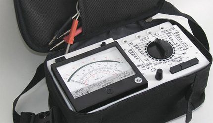
The measuring range of the device according to voltage (alternating) should have an upper limit of at least 600 V. The very principle of testing is the same as checking with a lamp. Only instead of the backlight, the instrument scale will already be used for control.
Step-by-step verification performance with a pointer tester:
- Set AC voltage measurement mode.
- Set the measuring range to 600 V.
- Connect the probes of the device to the contactors of the socket (phase - zero).
- Record the readings on paper.
- Connect one test lead to the ground contactor.
- In turn, connect the second probe of the device to the socket contactors.
- Record the readings on paper.
Now you should compare the recorded readings obtained during the verification process in step 6. If either of the two readings is equal to or slightly less than the value obtained in step 4, this means that the ground bus is working. The absence of any indications of the device indicates a non-working or ragged “ground”.
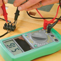
Similarly, the procedure is performed by a digital voltmeter equipped with a liquid crystal display. Here the only difference in the work is a more convenient perception of the measurement result. The digital analogue of the dial gauge is a multimeter. It is convenient in that it displays the measurement result on the screen in the form of digital values. Meanwhile, the degree of reliability and accuracy of measurements is inferior to the switch instrument.
A detailed instruction for checking the voltage in the outlet is presented in this article.
When you need to open the outlet
By and large, all of the above methods for testing the presence of grounding can be performed without removing the outlet cover. But then guarantees of 100% are not possible for one simple reason.
Often, in practice, there are examples when the grounding bus of someone "skillful handles" is connected to the zero bus. This is done by a wire jumper installed between zero and the ground contactor.
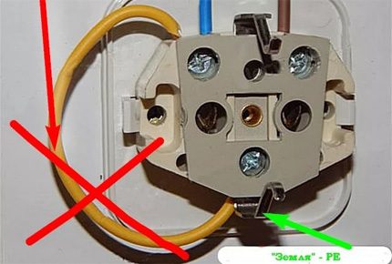
Without dismantling the cover, such a "work of art" cannot be found. At the same time, a check with instruments will show the presence of land. There is a risk of error. Therefore, opening the lid is always relevant in case of verification.
From the point of view of security for users with outlets, connecting the “zero” to the “ground” looks like an extremely unsuccessful and unacceptable action.
The ground bus, according to the rules of electrical installation, is always considered a separate communication line, indirectly tied to wiring diagram in the apartment or house.
And the neutral conductor at any time by negligence or inexperience of the operating personnel can be moved to the phase conductor. The consequences are clear without a word.
The use of grounded electrical outlets in everyday life is gradually becoming the norm. Now, every modern building is equipped with an electric facility, which provides for the mandatory installation of circuit elements with a ground bus to them.
This ensures a high degree of safety for people operating buildings using sockets for working with various household appliances.
Conclusions and useful video on the topic
The nuances of installing an outlet with grounding can be found using the video material:
By the way, it will be noticed: in the presence of a grounding bus in sockets, the degree of reliability of household appliances increases. Particularly critical to the lack of "ground" is the response of digital equipment, and such is now present everywhere.
Tell us which method you use to test the grounding in outlets. Share your own skills with readers, participate in discussions, and ask questions. The comment box is located below.

 How to check the voltage in the outlet with a multimeter: measurement rules
  Isolation of circuit breakers: insulation requirements for domestic and industrial appliances
  Common Outlet Malfunctions: How to Fix an Outlet Do It Yourself
  How to make two from one outlet and how to properly conduct an outlet from an outlet
  How to install and connect an outlet with grounding: learn to ground the outlet
  How to connect a double outlet: installing a double outlet in one socket
  How much does it cost to connect gas to a private house: the price of organizing gas supply
  The best washing machines with dryer: model rating and customer tips
  What is the color temperature of light and the nuances of choosing the temperature of the lamps to suit your needs
  Replacement of a geyser in an apartment: replacement paperwork + basic norms and requirements
I wanted to deal with the issue of the correct installation of grounding in sockets. Before that, there were old Soviet ones, in which there was no hint of the presence of grounding contacts. After reading a text that described in detail all the nuances of this process, I learned a lot about myself. A video was also useful, which clearly shows the connection of the outlet. A rather simple method of testing with a lamp is also described, I will definitely try it.
Good afternoon, Anton. Many accidents when testing electrical installations with incandescent lamps did not pass without a trace - an item prohibiting the use of lamps appeared in the "Safety Rules ..."
These rules, in addition, stipulate the qualifications of persons who are allowed to perform testing.Even the banal shutdown of the switch, which de-energizes the socket, is accompanied by a mass of insuring actions - among them, for example, hanging a poster prohibiting switching on.
I’ve attached a screenshot of a small section of the Rules, but try reading them to realize the difficulty of repairing or checking even an apartment outlet.
A rather difficult way with a light bulb. Is connecting a zero to the ground, the light will burn? And if at the entrance not only an automatic machine, but also an RCD is installed, it will not be knocked out, and the light will not light up. And if not neutral earthed, but isolated. I don’t know much, I got a hold of it, and I consider such recommendations unacceptable. The land of Russia is indestructible for all "craftsmen". It’s interesting, why do they connect zero to the ground so that it fucks someone.
Good day, Sergey. You haven’t figured it out - this is about your “Is it that having connected zero to the ground, the bulb will burn?” The author sets the following algorithm - the conductor going from the cartridge touches the “ground contact”, and the contacts of the socket alternately touch the other conductor.
Regarding the RCD or the machine that will be knocked out - after all, they do not knock them out of the switched on load. Just the role of the load is performed by a light bulb.
About “zero” and “ground” - these circuits are connected in the apartment panel (there are other options), and before that they go separately: working current flows through “zero”, nothing flows through “ground” connected to the metal housing of the electrical installation (for clarity, attached a screenshot).
In case of a short circuit to the case, the current begins to flow through two conductors - "ground" and "zero", which significantly reduces the resistance of the equivalent circuit. However, this is already difficult for you electrical engineering, but still attached a screenshot.
I always check the ground with a light bulb. For me personally, this is the easiest way. To begin with, it is necessary to isolate the entire structure well and be sure to take a working light bulb. And then they somehow checked with a friend, they thought that they “messed up” somewhere, but the whole point is in it. If the residual current device trips, then the whole system works as it should.
Dmitry, read my answer to Anton above.