The layout of the water supply pipes in the apartment: common schemes and options for implementation
Water is a key element in the life support of every home. And competent wiring of water supply pipes in the apartment allows for an uninterrupted supply of water to all points of water intake - plumbing and equipment.
The design of the system is based on hydraulic calculation, determination of probable pressure losses and the choice of pipe diameter. An important value will also be played by the wiring diagram itself - collector or serial. Agree, at first glance, everything seems complicated and confusing. However, it is not.
We will help to deal with the nuances of arranging the internal water supply network, we will outline the principles and layouts of the highway. Having studied the material, you will cope with the design and wiring of water pipes yourself.
The content of the article:
- Design of water supply in the apartment
- Hydraulic calculation of apartment water supply
- Calculation of the diameter of water pipes
- Calculation of losses of water pressure
- Water Distribution Schemes
- Pipes for residential water supply
- Metal pipe joints
- The nuances of the assembly of plastic pipes
- Conclusions and useful video on the topic
Design of water supply in the apartment
Preparation of the correct water distribution wiring project will allow avoiding problems both at the stage of pipe installation and later, when using water-consuming equipment.
You should accurately determine the list of plumbing and water-consuming stationary household equipment, the installation of which will be carried out in the apartment. Then draw a plan of the apartment on a scale, designate on it the positions of devices requiring connection to the water supply.
It remains to determine the scheme for decoupling the pipeline, taking into account the plan for all water-consuming stationary equipment. In addition to water consumers, the diagram indicates equipment that is part of a water supply system (water meters, pumps, etc.), the length of pipeline sections and pipe diameters.
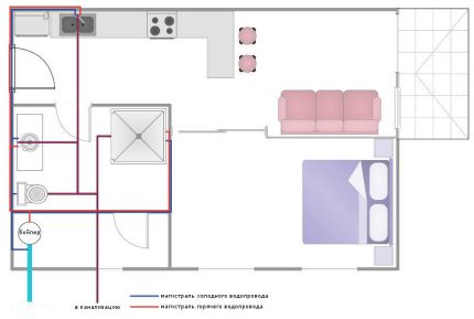
Ideally, the circuit should take into account the positions and characteristics (size, type) of adapters, fittings, couplings, etc. However, this is only feasible for plumbing. It’s easier to prepare a project without these “details”, go with it to a plumbing shop and show the project to the seller. He will help you choose the necessary "small" components.
But before you go for pipes and fittings, you need to make a hydraulic calculation of the design of the water supply system. This will make sure that there is no significant drop in pressure in the designed water distribution system, its ability to provide water to all consumers during their simultaneous operation.
Hydraulic calculation of apartment water supply
Under the hydraulic calculation of the water supply means the calculation of three parameters:
- water consumption in individual sections of the pipeline;
- water speed in the pipeline;
- pipe diameterat which a drop in pressure will be acceptable.
If, taking into account losses due to movement along the pipeline, the pressure turns out to be lower than normal, installation of a stimulation pump at the water supply will be required.
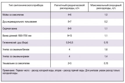
It is possible to establish the standard water consumption for a certain sanitary equipment either from its data sheet, or, in a generalized format, according to SP 30.13330.2012 (Appendix A1).
Information on the normative consumption from the above application, applicable to household plumbing, is indicated in the table in the picture.
high risk of insufficient pressure. This is especially true for consecutive pipelines (+)
Since the plumbing fixtures in the apartment are in the circuit of one water supply network and their simultaneous use is expected, the costs are summed up.
For example, in the apartment water supply network there is a washbasin, a shower and a toilet bowl, the simultaneous operation of which is quite possible. We summarize the largest second flow rates of the first two devices: 0.15 + 0.2 = 0.35 l / s.
In relation to the toilet, the table shows the maximum water flow per second for flushing, not for dialing the tank. Therefore, you need to count in seconds the average hourly consumption for this plumbing fixture: 4: 3600 = 0.0011 l / s. The total second flow rate for three devices will be: 0.35 + 0.0011 = 0.3511 l / s.
Calculation of the diameter of water pipes
The cross section of the water pipe, more precisely the cross-sectional area, is determined by the formula:
S = π2,
Where:
- S - pipe cross-sectional area, m2;
- π - the number "pi" with a sufficient value of 3.14;
- r - radius of the internal section, m
As a rule, with respect to steel pipes, the value of the radius is equal to half the value of their nominal pass (ДУ). In plastic pipes, the nominal outer diameter and inner diameter usually differ by a step. For example, in a 40 mm polypropylene pipe, the inner diameter is approximately 32 mm.
Using only the formula for calculating the cross-sectional area of the pipes, it will not be possible to calculate the necessary throughput parameters of the water supply.
It is necessary to use one more formula:
Q = V · S,
Where:
- Q - water consumption, m3;
- V - water flow rate, m / s;
- S - pipe cross-sectional area, m2.
Standards for domestic water supply systems limit the range of water velocity in the range of 0.7-1.5 m / s. If the water will move at a faster speed, then the water pipes quite noisy. We define the internal section of the pipeline, taking into account the highest permissible water velocity.
when the pressure drops in the 16 mm pipeline due to insufficient cross-section, the booster pump will not help (+)
First, we translate the calculated water flow using the above calculated data for the washbasin, toilet and shower, in cubic meters per second: 0.3511 · 0.001 = 0.0003511 m3/with.
Now it will be possible to calculate the minimum cross-sectional area of the pipeline by applying the second formula and entering the maximum permissible value of the water velocity: S = 0,0003511: 1,5 = 0,000234 m2.
We determine the radius of the internal cross-section of the water supply system according to the first formula: r2= 0.000234: 3.14 = 0.00007452. We calculate the root of the obtained value and get: r = 0.00863 m. Accordingly, in millimeters the radius of the internal section will be 8.63 mm.
Multiplying the obtained value of the radius by two, we find the required diameter of the pipe for the water supply: 8.63 · 2 = 17.26 mm. Those. the optimum pipeline remote control is 20 mm (rounding up).
Calculation of losses of water pressure
The formula for determining the pressure loss in a pipeline of a certain length is as follows:
H = iL · (1 + K),
Where:
- H - the magnitude of the pressure loss, m;
- i - hydraulic slope of the pipes of the water supply network of the apartment;
- L - length of water pipes, m;
- K - coefficient related to the purpose of the water supply network.
For drinking water pipelines, the K coefficient is 0.3.
In general, the greatest difficulty with this formula arises with respect to the obscure parameter “hydraulic slope”. By it is meant the resistance to movement of water exerted by the pipe.
Parameters affecting hydraulic slope:
- Water speed. More speed - higher hydraulic resistance of the pipeline.
- Diameter of water conducting pipe. The smaller it is, the higher the value of hydraulic resistance.
- The degree of smoothness of the inner walls of the pipe. This characteristic depends on the material of the pipeline (pipe made of HDPE is smoother than steel) and the duration of its service (lime deposits, rust).
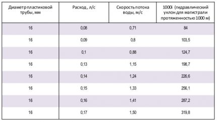
The most convenient way to calculate the hydraulic slope is the F.A. table Sheveleva. Using it, it will be possible to relatively quickly determine the hydraulic slope taking into account the diameter, material of the pipeline and the speed of water.
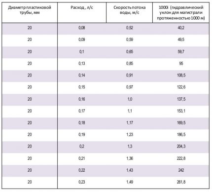
you will either need to build a highway on the collector comb, or use a 20 mm pipe (+)
However, the information from the Shevelev table is somewhat outdated - modern plumbing works under higher excess pressure than plumbing fixtures of the last century. Today is normal excess pressure in apartment water supply must be at least 0.3 kgf / m.
Let us perform, as an example, the pressure loss in a water supply system made of a plastic pipe of 20 mm diameter, with a total length of 23 m and the highest water velocity of 1.5 m / s.
The hydraulic slope for the pipeline with the above parameters will be 232.7, provided its length is 1000 m (1000i). To find the value of i used in the formula for calculating the pressure drop, it is necessary to divide by 1000, i.e. 232.7: 1000 = 0.2327.
Given the value of the coefficient of 0.3 (drinking water supply), we calculate the formula: H = 0.2327 · 23 · (1 + 0.3) = 6.95 m.
Those. excess pressure at the last (end) plumbing fixture of 0.5 atmospheres will be achieved if the pressure in the domestic water supply network is 0.5 + 0.695 = 1.195 kgf / cm2.
Since the pressure in the main pipeline is usually not lower than 2.5 atmospheres, the condition for the functioning of the water supply system considered in the example is quite met.
Water Distribution Schemes
The choice of the optimal connection scheme for water-consuming sanitary equipment depends on the number of consumers, the stage of repair, in which the apartment is located and the financial capabilities of its owner.
Today, the two most common methods for distributing water supply to in-house consumers are:
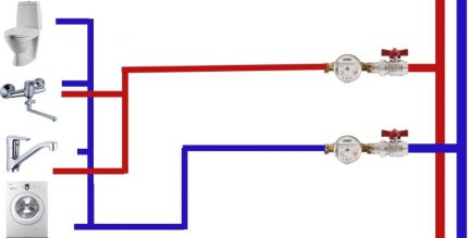
- Sequential. From the risers supplying water, the only pipeline of the main type is withdrawn, alternately supplying plumbing and household appliances.
- Collector. Through a water distributor, called a "comb", the liquid enters the consumers in the apartment through separate pipes.
Often, in the apartment water supply systems, both types of wiring are combined, it is convenient and profitable. Consider these schemes in more detail.
Sequential water distribution
When planning the construction of an apartment water supply on tees (sequential), it is important not to make a mistake with the diameter of the pipes. Correctly choose the cross-section of the highway will allow, including the calculation of water pressure losses.
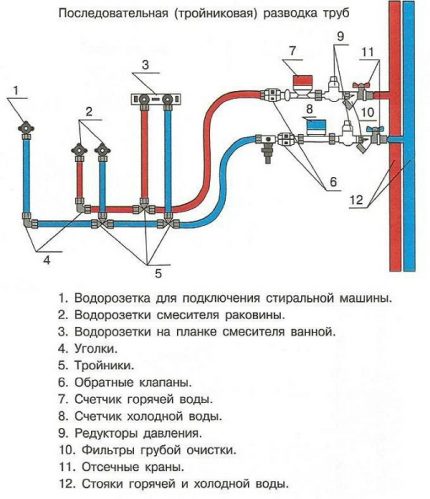
This method of building water supply in apartments was widely used in the Soviet past for the following reasons - small housing area, simplicity and low cost of work.
The disadvantages of the serial line are expressed in a significant decrease in water pressure on the latest plumbing equipment connected to it. In hot water systems, water cools significantly, you have to lower it and wait until the liquid of the required temperature reaches the consumer through the pipe.
However, with a small length of the water supply system, the choice of a tee supply scheme justifies its comparative cheapness.
Collector water supply for the apartment
From a serial pipeline, the collector line is distinguished by the permissibility of using pipes of a smaller section without loss of pressure. An induction water pump on the comb is not needed.
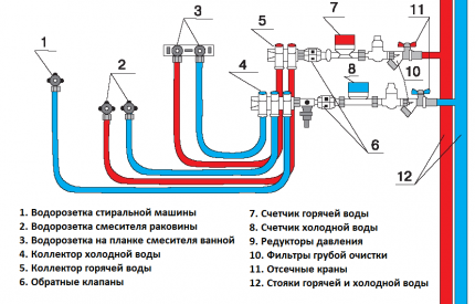
For large apartments, this fan distribution is ideal.
First of all, the volumes of water supply to each individual pipeline allow precise adjustment. Special mechanisms on the collector "comb" are configured to supply the required volume of fluid.
This is especially convenient for controlling domestic hot water - at any time, you can reduce the flow of hot water to a specific point of consumption. But collector water circuits have a complex architecture and need more pipes for construction.
Pipes for residential water supply
Exactly water pipe material determines the possible ways of their installation. In everyday life, pipes are used in four main types: steel, copper, metal, and flexible pipes called plumbing.
Steel pipes are the most durable, and therefore reliable. Therefore, in apartments, all wiring connected to the water risers is made only of steel. The most resistant to rust are galvanized steel pipes.
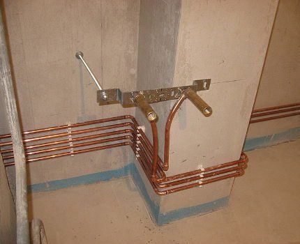
build. Soldering copper communications segments is not an amateur task
The water supply system is assembled by means of welded and socket joints, as well as using press fittings for steel pipes. For galvanized pipes, welding is not applicable, since it will destroy the protective layer.
High reliability and durability characterized by copper pipesbut they are the most expensive. Copper pipes have high heat dissipation; thermal insulation is mandatory for them. The connection of copper pipes is carried out by capillary soldering and by flanges - threaded and press fittings.
With all the convenience of plastic pipes as water communications, they have operational limitations - work with water at a temperature of less than 95 ° C and under a pressure of no higher than 10 atmospheres. The assembly of the PVC segments during the construction of the water supply network is carried out using special fittings.
Most common plastic pipes. They are well suited for indoor wiring in the apartment. The main disadvantage of plumbing metal plastic is its low resistance to mechanical damage. Such pipes are mounted only with a tab in the wall, they can not be displayed openly.
A flexible plumbing hose is enclosed in a metal winding. Thanks to the winding, it is able to hold high pressure, but is unstable to external damage.
This type of eyeliner is used within the boundaries of a single room, for example, to connect a sink, dishwasher or washing machine, water heater to a water source.
Metal pipe joints
Fixing pipe sections in this way is performed on a threaded connection. The connected pipe sections must have an internal thread (one segment) and an internal thread (second segment). Threaded diameters are indicated in inches. Threads are made with diameters 1/2, 3/4, one inch, one and a half, two inches, etc.
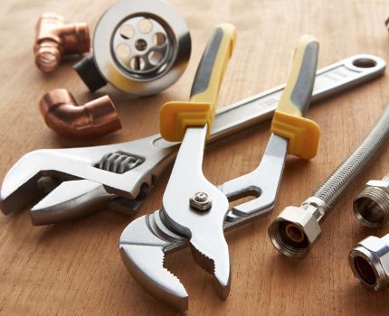
will allow you to tighten the nut and hold the pipe, and perform these work with one hand
Distinguish between pipe and fixing threads. The first is cut into pipes, the second into couplings and other fasteners (fittings).
To combine the two rigidly fixed sections of the pipeline, detachable joints are used - overhangs. A long thread is made on one pipe segment - sufficient to completely tighten the coupling and lead to the second segment with short cut threads.
It remains to unscrew the coupling from the first pipe to a short thread of the second, connected to the first.
The assembly order of the drive is as follows:
- To seal a short thread, a linen winding is screwed onto it, smeared with oil paint (for example, minium). You can rewind with plastic fum tape.
- A lock nut is screwed onto the pipe section with a long thread. It is necessary for fixing the coupling.
- The coupling is screwed onto a long thread until the lock nut.
- Aligning the pipes to be connected, screw the sleeve onto the short thread section. It remains to tighten the section of long thread between the lock nut and the coupling with a flax strand, screw the lock nut onto the coupling so that the seal is in the lock nut chamfer.
To form the drive, it is convenient to use special pipe wrenches - Volevach and double-lever systems.
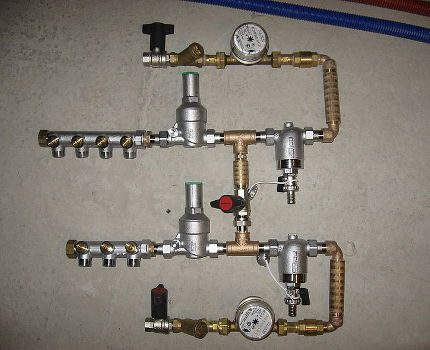
the distribution unit will be the most reliable, its segments are guaranteed not to weaken
In addition to couplings, metal pipes can be joined by press fittings designed for copper or steel pipes. Press fittings look similar to ordinary couplings, but have additional equipment - sealing rings. The latter are used for crimping pipes (special clamps are needed), connected by a press fitting fitting.
The most durable welded joints, however, only a specialist is able to perform them qualitatively. Recall that galvanized pipes cannot be welded, since a layer of zinc will come off.
The capillary soldering used in the construction of the run on a copper water pipe is carried out by a burner developing a temperature of 150aboutC. The solder melts in a 0.4 mm gap (no more!) Between the fitting and the pipe, firmly connecting the water segments. Note that such a soldering is carried out only by a professional, non-specialist can not do it.
The methods for connecting copper pipes will be presented by the following photo selection:
The nuances of the assembly of plastic pipes
Installation is carried out with a special tool: pipe scissors, calibrator, mandrels for deflection of pipes (internal and external), a press tool and wrenches.
The connection of metal-plastic pipes is usually done by compression or press fittings. The principle of mounting the overhangs through compression fittings is quite simple, based on a threaded connection. Assembling using press fittings is more difficult, consider it in more detail.
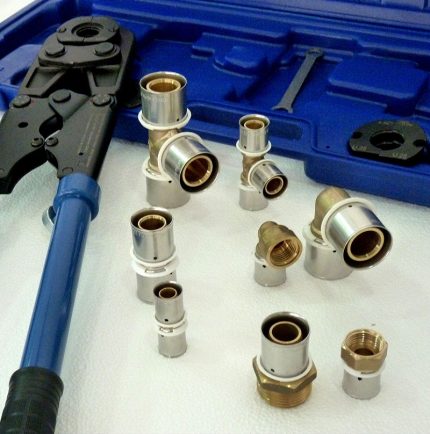
The design of press fittings used in the assembly of metal-plastic communications includes an internal fitting and a compression sleeve. In the center of the press fitting is a ring made of plastic-dielectric.
Before starting the installation, the pipe is trimmed, while the place of the cut on it changes its shape to oval.For returns to the end of a round plastic pipe, a special tool is used - a calibrator.
Outwardly, it resembles a multi-tiered children's pyramid, only fixed rings. To align the cut end of the pipe to a certain radius, the calibrator is screwed into it using the handle.
To mount the compression fitting, it is necessary to install a nut with a split ring on the pipe in series, carefully insert the fitting into the pipe, and then tighten the nut.
To make the connection with a press fitting, a crimp ring is inserted on the pipe, then a fitting is inserted and, using press ticks the sleeve is crimped.
The metal-plastic pipe is mounted on surfaces using special clips previously fixed to the floor or walls.
Since plastic pipes bend well, cutting them with fitting in the bend zone is not necessary. To give such a pipe a curved shape, internal or external flexible mandrels are used.
Conclusions and useful video on the topic
Assembling a water pipe from metal-plastic pipes performed by a master plumber:
Practical video instruction on installing couplings for metal-plastic pipes, installation of overheads and intermediate sections of water supply:
Video tutorial on capillary soldering of copper pipes for a water main:
Rules for choosing polypropylene pipes for water supply:
Building a workable water supply system in an apartment is impossible without attention to detail at every stage - designing, performing hydraulic calculations or assembling the selected wiring diagram. However, relying on standard solutions or building an efficient water supply system for years to come is up to you.
Share with your readers your personal experience in organizing water pipe routing. Please leave comments on the article, ask your questions and participate in discussions of the material. The feedback box is below.

 Water distribution in the apartment: typical schemes + design nuances
  DIY plumbing installation: classic wiring diagrams and installation instructions
  Hydroarrow for heating: purpose + installation diagram + parameter calculations
  How much does it cost to connect gas to a private house: the price of organizing gas supply
  The best washing machines with dryer: model rating and customer tips
  What is the color temperature of light and the nuances of choosing the temperature of the lamps to suit your needs
  Replacement of a geyser in an apartment: replacement paperwork + basic norms and requirements