Do-it-yourself time relay: an overview of 3 homemade options
You can activate and deactivate household appliances without the presence and participation of the user. Most of the models produced today are equipped with a timer for automatic start / stop.
What if I want to manage obsolete equipment in the same way? Be patient, with our advice and make a time relay with your own hands - believe me, this homemade product can be used on the farm.
We are ready to help you realize an interesting idea and try our hand on the path of independent electrical engineering. For you, we have found and systematized all the valuable information about the options and methods for manufacturing relays. Using the information provided guarantees ease of assembly and excellent operation of the device.
In the article proposed for study, the self-made versions of the device tested in practice are examined in detail. Information is based on the experience of masters keen on electrical engineering and regulatory requirements.
The content of the article:
Scope of a timer
Man has always sought to make his life easier by introducing various devices into everyday life. With the advent of motor-based technology, the question arose of equipping it with a timer that would automatically control this equipment.
Turned on for a given time - and you can go do other things. After a set period, the unit will shut itself down. But for such automation, a relay with a self-timer function was required.
A classic example of the device in question is in a relay in an old Soviet-style washing machine. On its body there was a pen with several divisions. Set the desired mode, and the drum spins for 5-10 minutes, until the watch inside reaches zero.
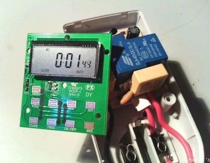
Today time relay set in various techniques:
- microwave ovens, stoves and other household appliances;
- exhaust fans;
- automatic watering systems;
- lighting control automation.
In most cases, the device is made on the basis of a microcontroller, which simultaneously controls all other operating modes of automated equipment.It’s cheaper for the manufacturer. No need to spend money on several separate devices that are responsible for one thing.
According to the type of element at the output, the time relay is classified into three types:
- relay - the load is connected through a "dry contact";
- triacs;
- thyristor.
The most reliable and resistant to bursts in the network is the first option. A device with a switching thyristor at the output should be taken only if the connected load is insensitive to the form of the supply voltage.
To make a time relay yourself, you can also use the microcontroller. However, homemade products are mainly made for simple things and working conditions. An expensive programmable controller in such a situation is a waste of money.
There are much simpler and cheaper designs based on transistors and capacitors. Moreover, there are several options, there are plenty to choose from for your specific needs.
Schemes of various homemade products
All the proposed manufacturing options do-it-yourself timers are built on the principle of starting the set shutter speed. First, a timer starts with a predetermined time interval and a countdown.
An external device connected to it starts to work - the electric motor or light turns on. And then, upon reaching zero, the relay gives a signal to disconnect this load or shuts off the current.
Option # 1: the easiest on transistors
Transistor-based circuits are the easiest to implement. The simplest of them includes only eight elements. To connect them, you do not even need a board, everything can be soldered without it. Such a relay is often made to connect lighting through it. Pressed a button - and the light is on for a couple of minutes, and then it turns off.
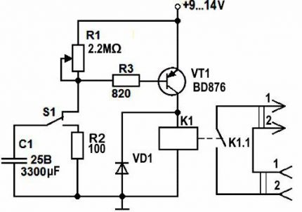
To assemble this home-made time relay, you will need:
- a pair of resistors (100 Ohm and 2.2 mOhm);
- KT937A bipolar transistor (or equivalent);
- load transfer relay;
- 820 ohm variable resistor (to adjust the time interval);
- 3300 uF capacitor and 25 V;
- rectifying diode KD105B;
- switch to start the countdown.
The time delay in this timer relay is due to the charging of the capacitor to the power level of the transistor key. While C1 is charging up to 9-12 V, the key in VT1 remains open. External load powered (light on).
After some time, which depends on the set value on R1, the transistor VT1 closes. Relay K1 is finally de-energized, and the load is disconnected from the voltage.
The charging time of the capacitor C1 is determined by the product of its capacity and the total resistance of the charging circuit (R1 and R2). Moreover, the first of these resistances is fixed, and the second is adjustable to specify a specific interval.
The time parameters for the assembled relay are selected empirically by setting various values on R1. To subsequently make it easier to set the desired time, markings with per-minute positioning should be made on the case.
To specify a formula for calculating the issued delays for such a scheme is problematic. Much depends on the parameters of a particular transistor and other elements.
Bringing the relay to its initial position is performed by reverse switching S1. The capacitor closes to R2 and discharges. After switching S1 on again, the cycle starts again.
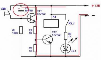
In a circuit with two transistors, the first is involved in the adjustment and control of the time pause. And the second is an electronic key to turn on and off the power at an external load.
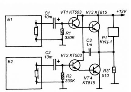
The most difficult part in this modification is to precisely select the resistance R3.It must be such that the relay closes exclusively when a signal is supplied from B2. In this case, the reverse inclusion of the load must occur only when B1 is triggered. It will be necessary to pick it up experimentally.
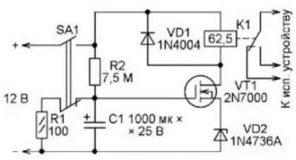
For this type of transistor, the gate current is very small. If the resistance winding in the control relay key is selected large (in tens of Ohms and MOhm), then the shutdown interval can be increased to several hours. Moreover, most of the time the relay timer practically does not consume energy.
The active mode in it begins in the last third of this interval. If the PB is connected via an ordinary battery, it will last a very long time.
Option # 2: Chip Based
Transistor circuits have two main disadvantages. It is difficult for them to calculate the delay time and before the next start it is necessary to discharge the capacitor. The use of microcircuits eliminates these shortcomings, but complicates the device.
However, even with minimal skills and knowledge in electrical engineering, making such a time relay with your own hands will also not be difficult.
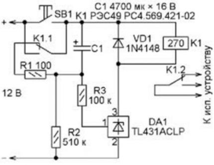
The opening threshold of the TL431 is more stable due to the presence of a voltage reference inside. Plus, for its switching, the voltage is required much more. At maximum, by increasing the value of R2, it can be raised to 30 V.
The capacitor to such values will be charged for a long time. In addition, the connection of C1 to the resistance for discharge in this case occurs automatically. In addition, you do not need to click on SB1 here.
Another option is the use of the "integral timer" NE555. In this case, the delay is also determined by the parameters of the two resistances (R2 and R4) and the capacitor (C1).
“Shutdown” of the relay occurs due to switching again the transistor. Only its closing here is performed by a signal from the output of the microcircuit, when it counts the necessary seconds.
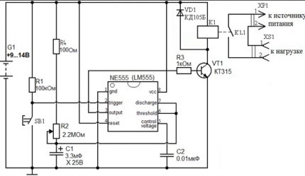
There are much fewer false positives when using microcircuits than when using transistors. The currents in this case are controlled more tightly, the transistor opens and closes exactly when required.
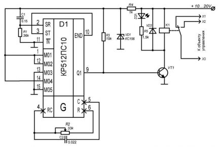
Another classic microcircuit version of the time relay is based on the KR512PS10 base. In this case, when the power is turned on, the circuit R1C1 supplies a reset pulse to the input of the microcircuit, after which the internal generator is started in it. The cut-off frequency (division ratio) of the latter is set by the control circuit R2C2.
The number of counted pulses is determined by switching the five pins M01 – M05 in various combinations. The delay time can be set from 3 seconds to 30 hours.
After counting the specified number of pulses at the output of the microcircuit Q1, a high level is opened, opening VT1. As a result, relay K1 is activated and turns the load on or off.
There are even more complex microcontroller-based time relay circuits. However, they are not suitable for self-assembly. It affects the complexity of both soldering and programming. Variations with transistors and simple microchips for domestic use are quite enough in the vast majority of cases.
Option # 3: for 220 V output
All of the above circuits are designed for 12-volt output voltage. To connect a powerful load to a time relay assembled on their basis, it is necessary at the output install magnetic starter. To control electric motors or other complex electrical equipment with increased power, you will have to do so.
However, to adjust household lighting, you can assemble a relay based on a diode bridge and a thyristor. At the same time, it is not recommended to connect anything else through such a timer. The thyristor passes through itself only the positive part of the sine wave of alternating 220 volts.
For an incandescent bulb, fan or heater, this is not scary, and other electrical equipment of this kind can not withstand and burn out.
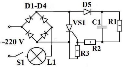
To build such a timer for a bulb, you need:
- resistance constant at 4.3 MOhm (R1) and 200 Ohm (R2) plus adjustable at 1.5 kOhm (R3);
- four diodes with a maximum current above 1 A and a reverse voltage of 400 V;
- 0.47 uF capacitor;
- thyristor VT151 or similar;
- switch.
This relay timer operates according to the general scheme for such devices, with a gradual charging of the capacitor. When closing on S1 contacts C1 begins to charge.
During this process, thyristor VS1 remains open. As a result, the load L1 receives a mains voltage of 220 V. After the completion of charging C1, the thyristor closes and cuts off the current, turning off the lamp.
The delay is adjusted by setting the value to R3 and selecting the capacitor capacitance. It should be remembered that any touch to the bare legs of all used elements threatens with electric shock. They are all under 220 V.
If you do not want to experiment and independently build a time relay, you can pick up ready-made options for switches and sockets with a timer.
Read more about such devices in the articles:
- A switch with a sleep timer: how it works and which view is better to choose
- Socket with a timer: types, principle of operation + installation features
Conclusions and useful video on the topic
It is often difficult to understand from scratch the internal structure of a time relay. Some lack knowledge, while others lack experience. To make it easier for you to choose the right circuit, we have made a selection of video materials that describe in detail about all the nuances of the work and assembly of the electronic device in question.
The principle of operation of the elements of the time relay on a transistor key:
Automatic timer on a field effect transistor for a load of 220 V:
DIY step-by-step delay relay manufacturing:
It is not too difficult to assemble a time relay yourself - there are several schemes for implementing this idea. All of them are based on the gradual charging of the capacitor and the opening / closing of the transistor or thyristor at the output.
If you need a simple device, then it is better to take a transistor circuit. But for precise control of the delay time, you will have to solder one of the options on a particular chip.
If you have experience building such a device, please share the information with our readers. Leave comments, attach photos of your homemade products and participate in discussions. The communication unit is located below.

 DIY Solid State Relay: Assembly Instructions and Connection Tips
  Time relay: operating principle, wiring diagram and tuning recommendations
  Voltage control relays: operating principle, circuit, connection nuances
  Pulse relay for lighting control: how it works, types, labeling and connection
  Solid State Relays: Types, Practical Applications, Wiring Diagrams
  Pressure switch for compressor: device, marking + wiring diagram and adjustment
  How much does it cost to connect gas to a private house: the price of organizing gas supply
  The best washing machines with dryer: model rating and customer tips
  What is the color temperature of light and the nuances of choosing the temperature of the lamps to suit your needs
  Replacement of a geyser in an apartment: replacement paperwork + basic norms and requirements
Interesting.Tell me, is it possible to connect the boiler through a relay powered by 220 volts? Is there a heater? And if I understand correctly, then the boiler should not fail due to the fact that only the positive part of the voltage passes? And by the way, do you plan to release a guide on how to make a book-lamp yourself? I saw several schemes on the Internet, but they are not very clear. And you have everything written in detail and clearly.
Good afternoon, Ilya. The article has a section “Option # 3: for power supply at an output of 220 V”, beginning with the words: “All of the above circuits are designed for a 12-volt output voltage. To connect a powerful load to the time relay assembled on their basis, it is necessary to install a magnetic starter at the output. ” In other words, no one includes TENs in the devices listed before this section.
Given the wording of your questions, I advise you to purchase a ready-made socket timer - the simplest 16-amp TRM-01 (daily setting of the response time - time setting step 30 minutes) costs 240 rubles. Outwardly similar electronic for 500 rubles. - TRE-01 for the same amperes - has advanced features (weekly schedule, setting step - 1 min.)
Regarding the “book-lamp” - everything is simple: to prevent the pages from catching fire, you need to use a battery-powered LED lamp. There is nothing complicated - it's a pity to spoil books.