Safety group for heating: device, principle of operation, rules for selection and installation
Person physically not can all time stay at boiler room for control serviceability the lines heating, temperature indicators and level pressure heating instrument. The main assistants at this the issue serve additional devices, automatically tracking functioning the system.
We will tell you which devices the group includes safety on the heating, how they work, how they protect the system. Based on our tips, you can easily select the necessary components. The article describes the assembly and connection rules for this important link responsible for trouble-free operation.
The content of the article:
Safety unit device
The main reasons for the malfunction of the closed-type boiler system are increased pressure or excessive filling of the pipeline with coolant, i.e., water. The boiler heat exchanger is the first device to respond to such deviations, which is why it fails.
Why can an accident happen?
To prevent such malfunctions in the heating system, a safety unit is used. With its help, the necessary pressure of the thermal carrier in the boiler, pipeline and batteries is achieved.
At the moment of excess pressure, excess of preheated heat carrier is discharged. Emerging emergencies, such as overheating of a water boiler, lead to an increase in pressure in the line. This process is the result of exceeding the temperature norm of the thermal carrier.
When heating, the liquid tends to expand, which the closed-type heating system is not designed for - include an additional reserve in its circuit expansion tank. However, its volume is also limited.
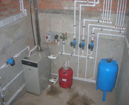
The consequence of the increased pressure is the failure of the boiler elements or a rupture of the line. To control the pressure and in the event of a potentially dangerous situation to adjust it to the optimum value, a mounted safety group will be needed.
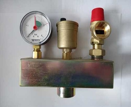
Structurally, the device is formed of the following modules: automatic air vent, pressure gauge and safety valve. All these devices are mounted in a galvanized steel case with threaded connectors, with or without thermal insulation.
Automatic air vent
In most cases, the automatic air valve for the security system is made of brass.
Air bubbles in the heating system appear due to such factors:
- initial filling of the heating line with liquid;
- installation of poor-quality or wear rubber seals;
- clogging by a corrosion deposit inside the pipeline;
- water recharge;
- incorrect installation or commissioning of the heating system, etc.
The water entering the heating circuit contains a lot of oxygen, which, through heating, begins to expand, forming air jams. Due to their formation, pressure increases, and the circulation rate of the coolant slows down.
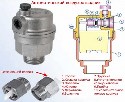
To prevent this from happening, it is advisable to install an automatic device for air discharge, which is convenient for use - it does not need to be adjusted with the participation of a person.
The principle of operation of the device depends entirely on the design features. The automatic device consists of a channel and a valve. The second element is responsible for the removal of excess air. If there is no excess pressure in the pipeline, the float is in the raised state and the needle valve in the “closed” position.
At the time of formation of the air plug, the float will lower, and the rocker will open the valve - this is how air is released from the system. After removing the excess, the float will return to its initial position and the valve will be closed again.
Pressure gauge - an accurate indicator of pressure
The pressure gauge is designed to measure pressure in the heating system. This device is designed to quickly obtain, verify and adjust the permissible degree of performance. Its main characteristic is the determination of accurate data.
In second place is such quality as reliability. For some, the size of the dial is important for easy viewing. Each switch mechanism has its own inaccuracy in measurement. This error is scattered as follows: at the edges of the scale it has a maximum value, in the center - a minimum.
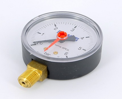
For each heating mechanism, the maximum permissible pressure level that it can withstand is prescribed in the accompanying documentation. Bars or atmospheres are used as measuring units in manometers. However, the first measurement option was widely used.
Bars have an intermediate value and are as close as possible to the physical and technical atmospheres:
- 1 bar = 10.197 m water column or 0.1 MPa
- Technical atmosphere (1 at) = 10 m water column
- Physical atmosphere (1 atm) = 10.33 m water column
1.5 atmospheres are standard pressure values in pipelines. independent heating systems. Therefore for autonomous boiler room a manometer with a maximum (end of scale) in 4 atmospheres will be enough.
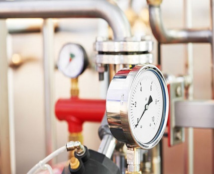
Safety valve features
In the heating system safety valve plays an important role. This is a safety device designed for heat generators. The main function is the elimination of loads (drops) in the event of unplanned situations. This problem is most relevant for steam heating systems.
However, increased pressure may occur due to such malfunctions:
- Due to a malfunction in the automation, the volume of the coolant may exceed the permissible norm.
- A rapid increase in temperature in the circuit.
This device also has a tendency to control the flow. coolant in the heating line. This is a stamped structure consisting of a brass body equipped with two parts - a membrane and a steel spring. As a rule, at the moment the fuse blows, to normalize the heating operation, it is necessary to eliminate about 100 g of the heated liquid.
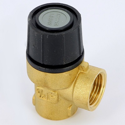
Due to the flexibility of the first element, the necessary pressure coefficient acting on the membrane is set. Therefore, the membrane septum overlaps the passage to the outside. By changing the compression ratio of the spring in the safety shutter, the functions of the protective mechanism in the heating system are regulated.
It is necessary to adjust the protective mechanism so that the maximum possible pressure indicator is 15% more than the working one. The valve adjustment process is carried out every year on the eve of the heating period.
The capacity of the device is checked by its forced opening. It is worth doing this with a certain frequency so that the discharge mechanism does not become clogged from various deposits, being in an idle position.
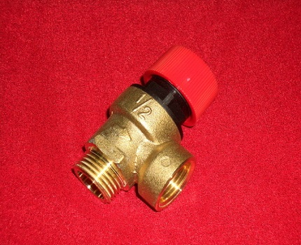
With the features of the action and installation of the safety valve for the boiler will introduce next article, in which the device is disassembled in detail and wiring diagrams are given.
The principle of operation of the security unit
The security group works according to an extremely simple scheme, where each of the modules is responsible for maintaining the norms of certain indicators in a private boiler room:
- Due to the convenient pressure gauge, the user can control the pressure readings at the time of filling the line with coolant, as well as during the operation of the boiler.
- The safety valve protects the heat generator from critical pressure drops.
- The main functionality of the air vent is based on the automatic descent of air entering the pipeline during its initial filling or during operation.
All safety modules are represented by a single link and are equipped with a special case - collector.
Provided that the open-type expansion tank is used in the boiler room scheme, the installation of the safety group does not make sense - the pressure in the pipeline is atmospheric, and excess air leaves the system through the tank's tank.
Rules for the selection of equipment
For each model of the protective unit, the parameters for which it is designed are prescribed in the accompanying documentation.
The main criteria that affect the choice of device:
- thermotechnical characteristics of the boiler, for which the unit is designed, kW;
- maximum temperature of the heat carrier, ° C;
- nominal pressure;
- compatibility with the heat carrier - water, steam or antifreeze;
- diameter of the connecting thread - if there is a mismatch, it will be enough to purchase adapters of the desired diameter.
The correct selection of the power of the safety unit provides reliable protection of the boiler from any malfunctions in the operation of the heating circuit.
Rating of popular models
Among the manufacturing companies involved in the development of safety valves, one can distinguish such popular companies: Watts and Valtec. The manufacturer Watts is famous for its rather extensive assortment of devices for the heating system, among which the safety unit occupies an important place.
The KSG series has various threaded housing devices that differ in their size (from standard to compact) and the material of manufacture:
- cast iron;
- steel;
- brass.
Additionally, some models come with heat-insulating covers. Units from the KSG line are characterized by a relief valve designed for a critical pressure of 3 bar. Installation in the heating main is carried out by means of a 1-inch connector with a female thread.
Valtec is not inferior in quality to its previous brand. The company presents a range of devices for boilers and expansion tanks - the VT 460 and VT 495 series, respectively.
The VT 460 range is designed for operation with domestic heating units up to 44 kW, with a maximum pressure of 3 bar. However, the prices of finished devices are far from cheap, so it’s advisable to call the decision to self-assemble such a unit.
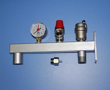
We assemble the security unit ourselves
In the manufacture of the safety unit should not be difficult.
To start the process, you will need to prepare the following modules and tools:
- relief valve;
- pressure gauge;
- air vent;
- wrench;
- gas keys;
- two squares with a threaded connection of external and internal type;
- fitting;
- crosspiece;
- adapters;
- sealant;
- plumbing flax for sealing and sealing joints.
Initially squares need to be screwed into a crosspiece. For tight joining, linen strands are wound onto the thread clockwise, while the distribution of the sealant on the surface should be the same.
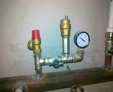
A thin layer of sealant is applied on top of the threads. Then, using a wrench, screw the squares into the crosspiece perpendicular to one another.
Now you need to install the pressure gauge, safety valve and air vent. If the parts have different diameters, appropriate adapters are used. After the final assembly of all modules, the operation of the mechanism must be checked under pressure - the device must not leak, and all parts must be in working condition.
Connection to the heating system
First of all, it is necessary to correctly determine the installation site of the security group.
There are certain requirements that must be observed:
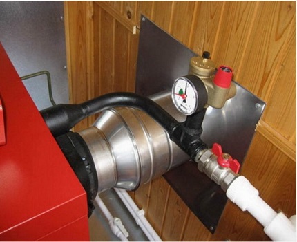
- it should be a horizontal section of the pipeline next to the heat generator;
- on the supply line after the boiler;
- in some boilers, it is provided to install a safety unit directly on the unit itself, for this there is a special connector on top of the heat generator;
- the distance from the heater to the protective unit must not exceed 1.5 meters, less is possible;
- for a pipe going vertically upward from the boiler, for example, to the next floor, it is necessary to equip the branching. This is done with the help of a corner so that the security group can be located in a horizontal plane and the units are looking "heads up";
- for a very powerful boiler, it may be necessary to equip another protective unit.
A very important rule to be followed is that valves between the safety group and the boiler are not mounted. It will be advisable to install a protective block to the first stopcock located on the line.
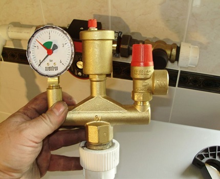
It is timely to check the operation of the safety valve. This procedure is performed using the following method - after installation, open the cap in the direction indicated by the arrow on the device.
After the installation of the protective device, it is necessary to check the correct operation of all modules. To start operation of the air vent, you will need to unscrew the upper cap and bleed air. Now the cover is returned to its original position, however, the device should remain ajar.
Conclusions and useful video on the topic
Video # 1. How to make a safety group for heating with your own hands:
Video # 2. Rules for installing the protective module:
Video # 3. Connecting the safety assembly to the polypropylene feed pipe:
Many are sure that the protective unit belongs to ordinary devices and its installation is not mandatory. However, a negligent attitude to this issue will not be able to protect the heating unit and the heating system itself from rupture as a result of a sharp pressure surge, which is a fairly common phenomenon in a closed circuit.
Please write comments, ask questions, publish photos on the topic of the article in the block below. Tell us how you equipped the heating circuit with a security group. Share useful information that may be useful to site visitors.

 Fire safety requirements for gas boiler rooms: subtleties of arranging rooms for gas boiler rooms
  The scheme of the boiler house of a private house: the principle of automation and equipment location
  DIY heating manifold: schemes and assembly features
  Window for a gas boiler house in a private house: legislative norms for glazing a room
  How to equip a boiler room in a private house: design standards and devices
  Press for fuel briquettes: options for manufacturing installations for pressing sawdust with your own hands
  How much does it cost to connect gas to a private house: the price of organizing gas supply
  The best washing machines with dryer: model rating and customer tips
  What is the color temperature of light and the nuances of choosing the temperature of the lamps to suit your needs
  Replacement of a geyser in an apartment: replacement paperwork + basic norms and requirements